


Laboratory load frames are adaptable load-testing devices that construction materials testing laboratories use daily to perform standard strength tests on geotechnical, soil mechanics, or asphalt specimens. Each test has unique requirements for the platen speed (strain rate) when loading the specimen, as well as the measurement and recording of loads and sample deformation. The specialized instrumentation required for each test is available as component sets or devices that are fitted directly to the load frame.
Limitations of Conventional Load Frames
A load frame must accurately regulate loading over a wide range of strain rates for maximum versatility across multiple material types and test methods. Load frames with limited platen speeds are not usable for the full range of materials and test methods. A testing lab with a daily schedule of triaxial soil tests might require a second load frame for unconfined compression or CBR samples or even a third if they wanted to run Marshall stability or other asphalt tests.
For example, the very slow strain rates required for ASTM D7181 consolidated/drained triaxial soil compression tests allow water to migrate out of the pores of fine-grained clays and silts to dissipate pore pressure. Conversely, asphalt samples tested for ASTM D6927 Marshall stability and flow are loaded at a much higher rate to simulate imposed traffic loads.
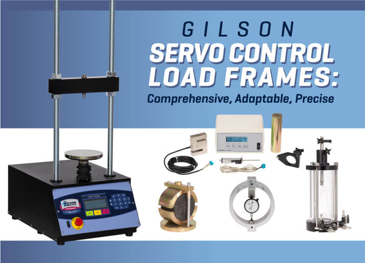
Gilson Servo Control Load Frames
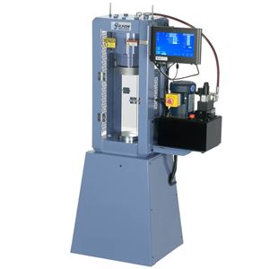
Servo Control Load Frames by Gilson bridge all the gaps for versatility and break new ground for accuracy tolerances. Two models have load capacities of 10,000lbf (44.4kN) or 20,000lbf (88.9kN), and both feature extra-wide platen speed ranges from 0.00001–2in/min (0.0001–50.8mm/min).
This uncommonly wide range satisfies the specimen loading requirements for all the popular soil mechanics tests, as well as asphalt tests based on the loading rate for Marshall stability samples (see the Test Method and Component chart below). Strain rates for some standard test methods are calculated for each specimen based on dimensions, axial strain percentages, and an estimated strength. Other tests prescribe a particular loading rate.
Closed loop electronic feedback of platen speed through the 2hp continuous servo motor ensures that there is no tradeoff of accuracy for the wide strain rate. Electronic regulation of the drive system governs the platen speed to ±1% of the selected set point, regardless of the load.
An advanced instrument console features simplified controls for time-saving vertical positioning of the bottom platen and one-touch shortcuts for commonly used strain rates. Setup and testing procedures are easy and efficient. A large emergency stop button enhances operational safety. The bright, four-line display is easy to read and shows the strain rate in real-time throughout the test.
A large 8in (203mm) bottom platen and 11.9 x 37.3in (302.2 x 947.4mm) WxH daylight opening ensures plenty of space when setting up larger specimens in sample testing fixtures and attaching test instrumentation. The solid steel horizontal crosshead adjusts quickly to the desired height on the 1.25in (31.75mm) coarse-threaded vertical rods.
Critical Factors for Load Frame Performance
We hope you ultimately select a quality laboratory load frame designed and built by Gilson. Whatever frame you choose, there are some basic considerations.
- Total Capacity should exceed the highest loads likely to be tested by about 20%. A load frame can occasionally be pushed to its maximum rated capacity if required. However, repeated loads at or near the maximum eventually degrade components and materials and shorten the service life. In addition to load capacity, the entire system must be rigid enough to minimize frame deflection, which can cause inconsistent test results, premature wear, and damage to the machine.
- Strain Rate (platen speed) must meet the requirements and tolerances for the desired testing applications. Test methods with low strain rates and close tolerances for speed often require higher overall strain accuracy. High-quality load frames apply platen speeds and forces smoothly across the entire loading spectrum.
- Daylight Opening is the maximum space between the two vertical rods, and from the top of the lower platen to the bottom of the horizontal crosshead. This dimension must be large enough to accommodate the specimen, fixtures, test cells, platens, and accessories once testing is underway.
- Bottom Platens support the specimen, test cells, and fixtures and must be thick enough to resist deflection under full load. Plated steel platens prevent corrosion caused by moisture from the specimens or test cells. Scribed concentric circles make it easy to center specimens and fixtures during setup.
- Horizontal Crossheads apply the forces from the drive system to the test specimen. Strength, rigidity, and ease of adjustment are essential features.
- Vertical Height Adjustment allows a range of sizes and types of specimens and test fixtures. Sturdy, coarse-threaded vertical rods with top and bottom adjustment nuts for the crosshead offer a simple system for quick and easy height adjustment.
- Controls should be simple and logically positioned to reduce operator errors. A large emergency stop button is an important safety feature.
- Test Components that integrate quickly and easily with the load frame simplify setup and conversion for other tests. Well-designed components are easily installed on different brands of load frames.
Tests and Testing Components
The best load frame falls short of its potential if not outfitted with high-quality testing components. Integrated component sets are an efficient way to equip your lab to perform standard test methods. Load and deflection measuring instruments are available individually for non-standard or research-based testing.
Component Sets
Each standard test has its own requirements for measuring applied loads and the resulting deflection, deformation, or penetration response from the specimen. Component sets for soils or asphalt tests are unique to each method and ensure the provisions of the test are met.
| Test Description | ASTM | AASHTO / Other | Digital Component Sets | Data Acquistion Software | Analog Component Sets |
|---|---|---|---|---|---|
| Unconfined Compressive Strength of Soils (UCS) | D2166 | T 208 | HMA-683D | HMA-611 | HMA-683 |
| Unconfined Compressive Strength of Soil Cement | D1633 | — | HMA-687D | HMA-612 | HMA-687 |
| California Bearing Ratio (CBR) of Soils and Base Materials | D1883 | T 193 | HMA-685D | HMA-609 | HMA-684, HMA-685 |
| Florida Limerock Bearing Ratio (LBR) for Base Materials | — | FM 5-515 | HMA-685D | HMA-609 | HMA-684, HMA-685 |
| Triaxial Shear of Soils, Unconsolidated/Undrained (UU) | D2850 | T 296 | HM-413, HM-414 | HMA-613 | HMA-686 |
| Triaxial Shear of Soils, Consolidated/Undrained (CU) | D4767 | — | HM-413, HM-414 | HMA-613 | HMA-686 |
| Triaxial Shear of Soils, Consolidated/Drained (CD) | D7181 | — | HM-413, HM-414 | HMA-613 | HMA-686 |
| Marshall Stability and Flow of Asphalt, 6in Specimens | D5581 | — | MSA-860D | MSA-134 | MSA-860 |
| Marshall Stability and Flow of Asphalt, 4in Specimens | D6927 | T 245 | MSA-860D | MSA-134 | MSA-860 |
| Indirect Tensile Strength of Asphalt (IDT) | D6931 | — | MSA-860D | MSA-134¹ | MSA-860 |
| Effect of Moisture on Asphalt (Lottman test) | D4867 | T 283 | MSA-860D | MSA-134¹ | MSA-860 |
| Tack Bond (Interlayer Shear Strength of asphalt) | — | T 407 | MSA-860D | MSA-134¹ | MSA-860 |
| Semicircular Bend Test of Asphalt | D4044 | T 393 | MSA-860D | MSA-134¹ | MSA-860 |
| Ideal RT Asphalt Test | D8360 | — | MSA-860D | MSA-134¹ | MSA-860 |
¹MSA-134 Marshall Data Acquisition Software is designed for asphalt stability and flow testing but can be useful for data collection from these test methods.
Individual Components
- S-Type Load Cells measure loads electronically based on tensile or compression forces. They are machined from stainless steel or nickel alloy and measure force in tension or compression to ±1.0% of full scale.
- Load Rings determine loads by measuring the deformation of the ring. Each ring is crafted from aircraft-grade anodized aluminum and includes a dial gauge and calibration curve for accurate force measurements.
- Digital Dial Indicators electronically track displacement and may be configured to provide measurements for data acquisition or upload to software apps.
- Mechanical Dial Indicators have an analog dial to track displacement. Indicators feature low-friction mechanisms and large, easy-to-read dials with clear graduations. Housings rotate 90° for convenient setup.
- Linear Variable Digital Transducers (LVDT) measure deformation, deflection, penetration, or other dimensional changes of specimens during testing and send data to a display or data acquisition equipment.
- Digital Display Readout Boxes interpret and display digital signals from load cells, LVDTs, and other electronic instrumentation. They also export values to testing software or spreadsheet applications on computers.
Analog or Digital?
Analog and digital measuring instruments each have their advantages. Whether guided by budget constraints or aiming for maximum testing efficiency, you can tailor your loading system for current and future needs with just some basic planning. Here are some points to consider before making your selection:
| Pros | Cons |
|---|---|
| Rugged and cost-effective | Can require reference charts to interpret readings |
| Simple to install and maintain | Requires experience and focus to use |
| Instrument accuracy meets test method requirements | Data must be recorded, calculated, and reported manually |
| Pros | Cons |
|---|---|
| Higher degree of accuracy and repeatability | Higher initial expense |
| Allows software integration for automated data collection, calculation, and reporting | Initial setup can take more time |
| Reduces training time and operator error | May require future software upgrades |
Data Acquisition Software
A superior load frame outfitted with quality testing components can automate or eliminate many manual processes, optimizing efficiency and reducing operator error. When data acquisition software applications are integrated with electronic measurement systems, data is automatically collected, displayed, calculated, and reported in real-time. Software is a big step forward for ease of operation, efficiency, and reduction of operator error.
Gilson Data Acquisition Software applications record loads and displacement, display real-time stress-strain data, and calculate and report results for popular soils and asphalt laboratory tests. Software for California bearing ratio (CBR and LBR), triaxial compression, unconfined compressive strength, soil cement, consolidation, shear, Marshall stability, and related asphalt tests, integrates with digital components, singly or in sets. All applications follow ASTM/AASHTO requirements for collecting and calculating results.
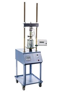
Alternative Laboratory Loaders
When exclusively or occasionally testing Marshall stability and related asphalt specimens, Marshall Stability Load Frames with dependable direct-drive motors are cost-effective choices. Their simplicity, reliability, and economy bring value to a lighter testing schedule. Both models can be used with HMA-860D Digital or HMA-860 Analog Component Sets and MSA-134 Data Acquisition Software.
We hope that this overview of Gilson’s Servo Control Load frames and quality testing components has helped you understand the potential of a versatile loading system for laboratory testing.
Gilson Is Here to Help
Contact our testing experts for more information or to discuss your testing application.
Testing Resources
Standard Test Methods, Specifications, and Practices
Individual test methods and specifications referenced in our product descriptions, blog articles, and videos are available for review or purchase from the professional organizations noted.
- ASTM International (American Society for Testing and Materials)
- AASHTO (American Association of State Highway and Transportation Officials)
- ACI (American Concrete Institute)
- State DOTs (Departments of Transportation)
- ISO (International Organization for Standardization)
- BS (British Standards)
- EN (European Standards)