


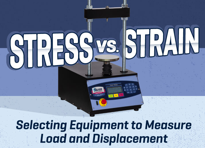
Achieve Accurate and Repeatable Load and Displacement Measurements
When you break down the details of test methods for just about any strength assessment performed in a construction materials testing laboratory, it comes down to one question: how much force (stress) is required to displace (strain) the material? Using axial loading, shear loading, or penetration force to test for strength is all about load and displacement.
Some of the more common tests for soils, asphalt, or other materials that depend on these principles include unconfined compression, direct or triaxial shear, consolidation, asphalt Marshall stability and flow, CBR penetration, and many more.
Analog & Digital Options
What are your options for measuring load and displacement when performing construction materials testing? Analog devices will do the job inexpensively for most applications, but digital equipment has distinct advantages. Advances in technology allow collection, storage, and analysis of data electronically, saving time and money, increasing accuracy and productivity, and reducing errors. The ready availability of stand-alone components means there are options when building a new system or when repairing or retrofitting an existing device.

Load Measurement
Measuring the amount of force applied to a soil specimen is the most fundamental step for testing strength. Load, load rings and load cells are stand-alone devices that measure these forces in compression or tension. Deadweight and pneumatic systems both apply loads in known units of force and may not use instrumentation for direct measurement of loads.
Load Rings
In the early 1920s, load measuring systems using hydraulic pistons or assemblies of concrete or cast-iron deadweights were unreliable, inconsistent, and impractical for applications requiring highly accurate measurements. H. L. Whittemore and S. N. Petrenko of the National Bureau of Standards (NBS), the forerunner to the National Institute of Standards and Technology (NIST), developed a reliable method of using a metal ring to precisely measure applied force.
Since they knew that a metal ring would react to applied loads by deflecting in a linear, predictable fashion, they designed a highly accurate device to measure the deflection.
A thin metal reed mounted on a micrometer screw is tapped to start it vibrating, and the screw is adjusted until the vibrating reed barely touches the opposite side and creates a distinctly different buzzing sound. Their proving ring accurately measured the applied forces at a fraction of the cost of other methods and dramatically reduced the logistics of handling sizeable loading weights. This method sounds archaic but can produce readings accurate from ±0.0125% to 0.075% and has only recently been improved upon by electronic imaging systems.

Photo Credit: www.nist.gov
Everyday laboratory testing does not require this extreme level of accuracy, so load rings substitute mechanical dial gauges or digital dial indicators to measure deflection, measuring applied forces to tolerances of ±0.5%.
The rings are machined from high-strength 6061 aluminum alloy and have capacities from 250lbf to 10,000lbf (1.1kN to 44.4kN). Each ring is load-tested at the factory and supplied with a unique calibration chart showing plotted force values. Load rings are analog devices, and data must be recorded manually, unless fitted with digital dial indicators configured for data transfer.
Load Cells
Surprisingly, the back story of modern electronic load cells starts even earlier than that of load rings. In 1843, Sir Charles Wheatstone, an English physicist, found that applying force to a metal element changes its electrical resistance. The concept was mostly experimental until modern electronics made it possible to produce strain gauges that provide reliable load measurements.
S-type load cells are strain gauges that measure force when elastically deformed in tension or compression. The S-shape of the cell forms three beams. Strain sensors on the center beam measure changes in electrical resistance as the two outer beams are loaded. The electrical signals convert to force values when captured by digital readout devices and data acquisition software.
The precision, cost-effectiveness, and ease of use of the S-type load cell make it very popular for the measurement of inline loads typically applied in laboratory strength testing. The threaded mounting holes on the top and bottom make the devices easy to install, and capacities range from 500lbf to 20,000lbf (2.2kN to 88.9kN).
Dead Weight
Producing known loads on a test specimen by hanging metal weights off of a beam is an ancient technology, but still has its place in modern laboratory methods. The practice is simple, cost-effective, reliable, and, when performed correctly, it is accurate enough for many applications.
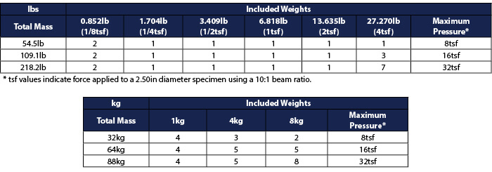
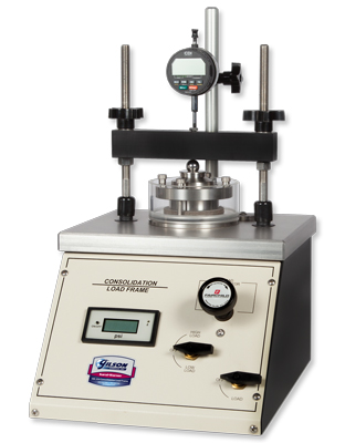
Deadweight systems often have multiple anchor points in the beam to create different lever ratios. More anchor points (ratios) allow for a greater variety of forces using the same weight sets. Dead weights are popular for use with soil consolidation load frames and to create vertical confining pressures in direct shear tests.
Pneumatic Loading
In the mid-1950s, Reuben Karol and Pat Warner developed the innovative CONBEL® system using air pressure to apply compressive forces in Karol-Warner soil consolidation load frames and confining loads for some soil direct shear machines.
Pneumatic loading has some advantages over other methods. The load against the specimen can remain constant regardless of how much the sample is compressed or deformed, and the forces can be applied or changed quickly without shock.
Displacement Measurement
With the application of force, a soil sample inevitably changes shape; consolidation specimens consolidate, shear specimens shear, and penetration samples are penetrated. Deformation, distance, or depth of penetration measurements are all crucial for comparison to loads in determining strengths for the different types of tests.
Mechanical Dial Indicators
John Logan, a watchmaker in Waltham, Massachusetts, patented the first dial indicator in 1883. The first mechanism consisted of a watch chain wound on a drum but was later improved to the rack and pinion system still in use today.
Mechanical dial indicators are inexpensive and reliable but require hands-on human involvement to monitor and record values. Most have only a single unit of measure. Models in common use for soil applications have capacities from 0.2 to 1in (5 to 25mm) and divisions of 0.0001 to 0.01 in/mm.
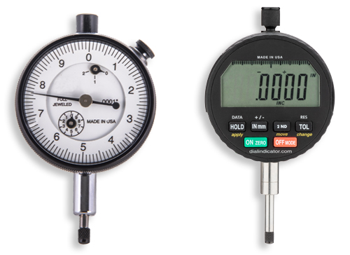
Digital Dial Indicators
Digital dial indicators are a step up from the mechanical versions. Electronically obtained values are displayed, and these devices can be equipped with an optional cable to transfer measurements to computer spreadsheets or other software programs. English or metric measuring units can be selected.
Because they have similar size and form factors to mechanical models, it’s often easy to upgrade older equipment inexpensively and without extensive modification. The measurement range is comparable to analog models, but the resolution is generally higher.
LVDT’s
Linear variable displacement transducers are sensors that produce electronic measurements based on the movement of an actuator's shaft. A separate data readout unit is required to display readings and to upload measurements to a computer. LVDT’s are an excellent fit for testing systems configured with software for automatic data acquisition, calculation, and graphing.
Data Collection & Reporting
Analog instruments such as load rings and mechanical dial indicators meet the requirements of most test methods and are effective and inexpensive when test methods are only occasionally performed.
Digital instruments like load cells and LVDT’s introduce the precision of electronic measurements to your testing and increase the flexibility of data handling. Analog or digital component sets for the most common tests are available.
Data readout units and software paired with electronic load and displacement sensors streamline reporting and increase production, accuracy, and repeatability.
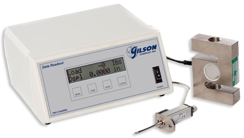
Data Readout Units
Data readouts collect input from load cells, LVDT’s, and other transducers on two or four discrete channels. Data displayed on-screen can be transferred to a PC and entered on spreadsheets, plotted in graphs, or included in software applications. Two-channel data readouts are available paired with S-type load cells and LVDT’s as kits for convenient customization of testing setups.
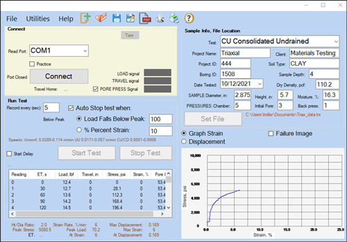
Data Acquisition Software
Adding software to your testing system to collect and process data from load and displacement instruments offers the most efficient method for accurate and cost-effective testing. Consistent, professional-looking reports are generated with little effort, and operator error is reduced or eliminated.
We hope this article has helped you understand the function of load and displacement instrumentation and how this equipment is used in construction materials testing applications.
Gilson Is Here to Help
Contact our testing experts for more information or to discuss your testing application.
Testing Resources
Standard Test Methods, Specifications, and Practices
Individual test methods and specifications referenced in our product descriptions, blog articles, and videos are available for review or purchase from the professional organizations noted.
- ASTM International (American Society for Testing and Materials)
- AASHTO (American Association of State Highway and Transportation Officials)
- ACI (American Concrete Institute)
- State DOTs (Departments of Transportation)
- ISO (International Organization for Standardization)
- BS (British Standards)
- EN (European Standards)