


Importance of Soil Sampling and Classification
Performing geotechnical and engineering tests on soils in the field is a combination of necessity and practicality. Soil is unique as a construction material because it occurs naturally and often remains in its natural state while in use.
Descriptions and classifications of soil samples are the most accurate and comprehensive when performed on fresh, minimally disturbed samples. Informed decisions for laboratory tests can be made, and initial sample preparation for lab tests can begin. Consistency, density, and bearing capacity estimates are useful during an initial evaluation of in-place soils. Field testing performed once a project is underway is a practical way to confirm laboratory results.
In this two-part blog post series, we will examine the range of soil evaluations, tests, and procedures that can be carried out on-site. Part 1 looks at field sampling and the visual classification of soils. Part 2 will cover various field tests of soil properties.
Geotechnical Soil Sampling
Sampling methods vary, but all offer the opportunity to examine, describe, and classify freshly sampled soils on the spot. The project scope and the requirements of the geotechnical design process determine the optimum sampling method.
Observations of changes in soil density, structure, and composition are essential and must be performed on-site. Decisions to modify the type or frequency of soil sampling can be made in the field without delay before work continues. Here are some standard sampling practices:
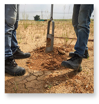
- Manual soil sampling equipment includes soil augers, soil sample probes, or shovels to collect soils from the surface or in shallow formations. Manual sampling is a cost-effective method for initial assessments of soil types or as a verification of project requirements. As a practical matter, sampling with hand augers becomes increasingly more difficult at depths of more than 5ft to 10ft (1.5m to 3m). These manual methods disturb the structure of the soil layers, but the samples are sufficient for visual classification and laboratory tests like Atterberg limits and particle size analysis.
- ASTM D1586 standard penetration tests (SPT) utilize a divided sampling tube (split-spoon) driven by a 140lb free-falling drop weight to collect a representative soil sample and measure the penetration resistance of the soil. Split-spoon samples are considered disturbed but can be intact enough to provide compressive strength or shear strength estimates. The SPT, or “N” blow count values estimate relative bearing strengths for structural foundation designs.
- "Shelby tube," or thin-wall samplers, provide intact, relatively undisturbed samples of fine-grained soils. When used according to ASTM D1587, they require the smooth downward driving force from the hydraulic system of motorized drill rigs.
- ASTM D6282 direct-push methods are sometimes employed when foundation design is not a factor, such as environmental or hydrological assessments.
Soil Sampling Equipment
- Soil sampling augers are available in a variety of designs for effective manual sampling of different soil types. Disturbed samples can be recovered from depths of 10ft to 15ft (1.5m to 3m) or more. Accessories for threaded or quick-connect systems include handles and extensions.
- Soil samplers (soil probes) efficiently sample surface layers and feature one-piece construction
- Shovels are useful for collecting bulk materials from a sampling site.
- Sampling bags retain large disturbed samples for basic laboratory testing. Twist-tie and tag accessories secure and identify samples.
- Sample containers and sample cans preserve field soil samples and prevent loss of moisture

Visual Classification of Soils
Visual classification of soil samples in the field by a trained and experienced technician is value-added for any project. A reliable classification performed on-site streamlines the selection of samples for advanced laboratory testing and ties together soil types and stratigraphy across the sampling area. Descriptions used in soil classifications must be consistent and coherent as well as accurate. Stakeholders in the design and construction process must be able to read the field description and relate it to the correct soil type. An in-depth discussion of laboratory and field soil classification methods is also covered in this previous blog post Soil Classification: Foundation and Pavement Design—It All Starts Here.
Worker protection and site safety also depend on visual classification and evaluation of on-site soil conditions, as discussed in our previous blog on trench safety. OSHA Publication 29 CFR 1926, Subpart P is very clear about the requirement for active assessment and classification of soils to establish the safety of excavated areas.
There are several unique soil classification systems for geotechnical engineering applications. Variants of these systems are used for specific applications or preferences. Geotechnical classification charts are essential references for visual classifications of soils. Classification systems in current use are listed below.
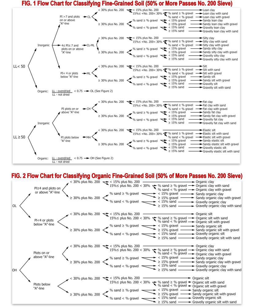
- The Unified Soil Classification System (USCS) described in ASTM D2487 is widely practiced and considered a common language when discussing soil classification for engineering purposes. Arthur Casagrande developed the system as the “Airfield Classification System” in the early 1940s in response to the need for the rapid construction of military installations. The system is established on particle size and soil plasticity values but does not describe moisture or density characteristics of the soil when freshly sampled.
- In 1929, Karl Terzaghi created a soil classification system for highway construction purposes. The system was later revised and adopted by the American Association of State Highway and Transportation Officials (AASHTO). Their method M 145 divides soils into eight classes based on a calculated group index (GI). The GI of a soil type is derived from the percent passing the No. 200 (75µm) test sieve, the liquid limit, and the plasticity index.
- The Modified Burmister System evolved from a technique developed by Columbia University Professor Donald Burmister in 1950. He recognized the need for a complete, structured description for quick and accurate use in the field. Burmister’s system uses words like “some,” “little,” or “trace” to indicate the proportions of grain sizes and standardized terminology to describe texture, structure, and color. Consistency, stiffness, and moisture are defined by manually manipulating the sample. Blow count ranges from the Standard Penetration Test (SPT) may be used to depict soil density.
Visual Soil Classification Equipment
- A soil pocket penetrometer or Geotester pocket penetrometer (dial pocket penetrometer) enables quick estimates of compressive strength on freshly-sampled soils. An accessory foot to test soft soils is available.
- The pocket shear vane tester measures the approximate shear strength of fine-grained soils.
- The Sand Grain size chart, geotechnical gauge, and sand gauge provide standard references for descriptions of particle sizes and shapes. Other information for descriptions of consistency and soil classes are included.
- Munsell soil color book ensures that standardized soil colors are used in field descriptions of soil.
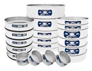
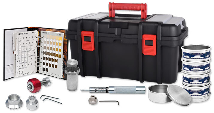
- A soil classification kit contains much of the equipment described above, as well as a set of 3in (76mm) diameter ASTM E11 test sieves for direct checks of particle sizes. Equipment is packed in a sturdy latching field case.
We hope this blog post has helped you understand the equipment and procedures used to sample and classify soils in the field. Be sure to look for the follow-up posting in this two-part series, where we examine tests on soils performed in a field setting.
Gilson Is Here to Help
Contact our testing experts for more information or to discuss your testing application.
Testing Resources
Standard Test Methods, Specifications, and Practices
Individual test methods and specifications referenced in our product descriptions, blog articles, and videos are available for review or purchase from the professional organizations noted.
- ASTM International (American Society for Testing and Materials)
- AASHTO (American Association of State Highway and Transportation Officials)
- ACI (American Concrete Institute)
- State DOTs (Departments of Transportation)
- ISO (International Organization for Standardization)
- BS (British Standards)
- EN (European Standards)