


Why Resistivity of Concrete is Important
Determining the electrical resistivity of concrete offers valuable insights into its long-term durability. Concrete resistivity is directly related to its ability to resist the penetration of harmful water-borne chlorides.
Water, with various salts in solution, readily penetrates permeable concrete. Chloride ions migrate into the pore systems, decreasing freeze-thaw resistance and kicking off the cycle of corrosion in the reinforcing steel. Permeability (resistance to fluid penetration) and chloride diffusion rates are critical measurements that predict performance and identify durable concrete.
Measuring Concrete Resistivity
The electrical resistivity measurement of saturated concrete has a very good correlation to permeability and chloride diffusion values. The ASTM C1202/AASHTO T 277 rapid chloride permeability (RCP) method can measure these values effectively, but it is strictly a laboratory test. Curing for RCP samples takes anywhere from a few days to several weeks, and extensive preparation is required to set the specimens up for testing. The ASTM C1556 test for chloride diffusion coefficient also has complex sample preparation and test procedures.
Two Types of Testing
Bulk resistivity and surface resistivity tests are two recognized and increasingly popular methods to estimate permeability and establish durability predictions.
Bulk Resistivity Testing
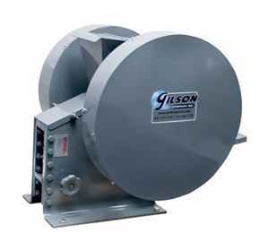
Bulk resistivity is performed by placing a metal electrode plate with conductive foam inserts at each end of a 4in (102mm) diameter test cylinder or core and measuring potential electrical values between opposite ends. The test is fast and straightforward when compared to the RCP method. However, the procedure still requires some sample preparation and is limited to cylindrical samples in the lab.
Surface Resistivity
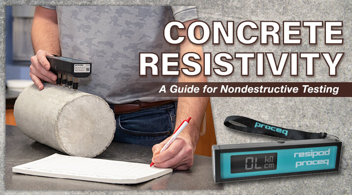
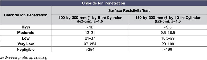
Surface resistivity tests employ the proven four-probe Wenner electrode array to measure electrical resistance. This practice was first used for geological applications in the early part of the 20th century and is now a reliable alternative to the RCP method for measuring concrete electrical resistivity. The AASHTO T 358 test method, published in 2011, describes the procedure, and an ASTM test method is pending. The Wenner array consists of four equally spaced electrodes. The external electrodes apply low-frequency alternating current on the moist concrete surface, while the inside probes measure electrical resistance. Qualitative terms express the electrical resistance to chloride-ion penetration.
The Proceq Resipod Concrete Resistivity Meter is designed for surface resistivity testing but easily adapts to perform bulk resistivity readings when connected to the Bulk Resistivity Accessory.
The Resipod quickly determines surface electrical resistivity and can be used on lab specimens or areas of any form factor in the field. Measurements are fast, require little sample preparation, and are completely nondestructive.
- Permeability and chloride diffusion estimates are quickly determined on lab specimens or structures in the field using the same instrument.
- Performing a series of tests on-site assesses uniformity of the structure and quickly identifies areas with differing permeability rates.
- Correlation of resistivity readings to rapid chloride permeability test values allows fast and efficient estimation of the rate and likelihood of reinforcing steel corrosion.
- Surface tests performed on concrete strength specimens before testing correlates resistivity values with curing rates and strength development.
- Surface resistivity readings can indicate relative variations in relative water/cementitious materials ratios.
- Areas of concrete with inconsistent resistivity readings are easily located and noted for follow-up examinations with half-cell corrosion meters, concrete moisture testing equipment, or concrete strength testing equipment.
Probe Spacing, Aggregate Size, and Reinforcing Steel
Aggregate particles are often non-conductive relative to the concrete mix as a whole, so probe spacing must exceed the size of the largest aggregate particle. At the same time, the presence of highly conductive reinforcing steel also has a significant impact on results, so optimum spacing should be less than the known distance between reinforcing bars.
AASHTO T 358 specifies a probe spacing of 38.1mm (1.5in) for their method, but other procedures have settled upon 50mm as the best compromise. The Resipod Meter has two fixed-probe model variants that meet each of these requirements. The geometric accessory is an optional probe attachment with variable probe spacing from 40 to 70mm (1.57 to 2.76in) to accommodate different aggregate sizes and bar spacing.
Testing Laboratory Specimens
Sample preparation for concrete cylinders tested in the laboratory is very straightforward. A moist surface is required on the specimens for testing, the same requirements for compressive strength testing. Simple straightedges and markers are used to mark the sample surfaces for positioning of the instrument. The surface material is scraped away for better electrical contact. If needed, the maximum resolution of the readings can be enhanced using foam contact pads.
After ensuring the probe reservoirs are filled with water, firmly press the instrument against the sample surface. Stable readings are displayed on the LCD and saved for later upload to a PC through a USB connection and included software. The Resipod detects insufficient electrical connections and displays relevant coded alerts to help correct them.
Testing Concrete Structures in the Field
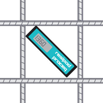
For field testing applications, reinforcing steel is located and marked using an accurate rebar locator or cover meter. Surface moisture conditions should be similar when comparing field resistivity tests to laboratory results. Usually, this means the test area should be moist when taking readings. Optimum orientation when positioning the probe array is diagonally within the space between reinforcing bars, as shown here:
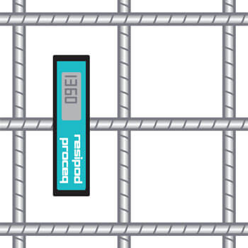
If the close spacing of the bars does not permit this, the instrument can be positioned perpendicular to the bars, straddling their position if necessary:
Rilem publication TC-154 EMC provides additional guidance on techniques for obtaining readings for electrical resistivity of concrete in situations where closely spaced reinforcing steel is an issue.
We hope this blog post on resistivity testing of concrete has provided some insight into methods and equipment.
Gilson Is Here to Help
Contact our testing experts for more information or to discuss your testing application.
Testing Resources
Standard Test Methods, Specifications, and Practices
Individual test methods and specifications referenced in our product descriptions, blog articles, and videos are available for review or purchase from the professional organizations noted.
- ASTM International (American Society for Testing and Materials)
- AASHTO (American Association of State Highway and Transportation Officials)
- ACI (American Concrete Institute)
- State DOTs (Departments of Transportation)
- ISO (International Organization for Standardization)
- BS (British Standards)
- EN (European Standards)