

Soil compaction is an operation common to most construction projects and increases the strength and stability of soils to support earthworks, structures, and pavements. Techniques to achieve maximum soil density are well known, and the outcomes can be tested and quantified using standard methods. Soil material is placed in layers, or lifts, in depths from a few inches to a foot or more, and compaction equipment rolls, kneads, vibrates, or sometimes uses dead-weight to consolidate the soil.
The Right Kind of Compaction Test
Specifications for soil compaction are established during the design phase of the project and depend on both total loads anticipated and whether those loads will be static or dynamic. Judging the adequacy of compaction efforts using qualitative measurements like penetration resistance or observation of wheel traffic is not sufficient to determine if the specifications have been met. Standard Proctor specifications (ASTM D698 / AASHTO T 99) work well to control compaction operations for installations like earth embankments and building pads.
Modified Proctor specs (ASTM D1557 / AASHTO T 180) are better suited for control of soil compaction in areas like pavements and airfield runways where heavy wheel loads create dynamic forces. Typical compaction requirements for a project may range from 90% to 95% of standard Proctor for non-structural areas to 98% or more of modified Proctor for heavily loaded pavements.
Laboratory Testing Sets the Benchmark
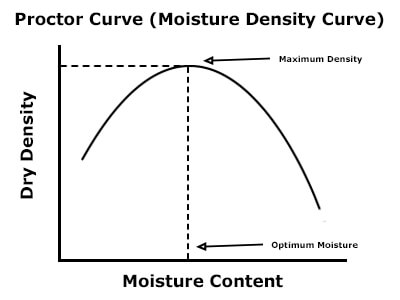
Proctor tests are soil moisture-density relationship tests that establish maximum dry density (the unit weight of the soil minus the weight of water) and the optimum water content for soil samples. For each soil type, the dry density and optimum water content values are different.
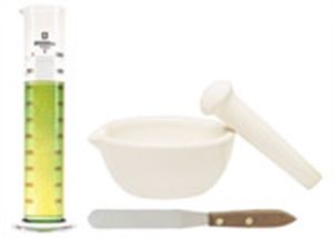
Water is added to four to six portions of the dried soil sample in increasing amounts. Each prepared portion is consolidated into a compaction (proctor) mold with a Proctor Hammer or Mechanical Soil Compactor and then is weighed and corrected for moisture content. The dry density increases as the added moisture lubricate the soil particles and enable greater compaction from the same applied energy. Once the optimum moisture content is exceeded, the water starts to displace the soil in a given volume, and the dry density decreases.
A graphic plot of the density versus moisture content creates a well-defined curve that shows the effect of moisture on the soil during compaction. For a deep dive into soil moisture/density relationships and Proctor test, see our Proctor Compaction Test: A Basic Guide blog post.
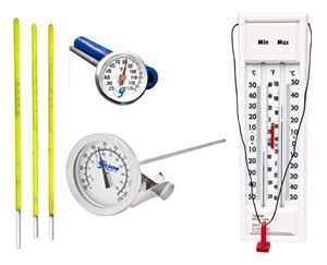
State transportation departments, or other regional authorities outline a “one-point” field test method (AASHTO T 272) to verify that the soil on-site is the same as the laboratory sample. This on-site compaction test is performed using the same type of mold, compaction hammer, and the number of blows as the original lab method. The moisture content is determined using a gas-pressure moisture tester or simple field dry-back methods. Density and moisture results are plotted against the original laboratory curve to confirm a match.
In situations where laboratory information is not available, the field point results may be compared to a family of curves compiled from local or regional soil data to select the best maximum density and optimum moisture curve. In some cases, two or three field points may be compacted at different moisture contents and compared to the curves.
Which Soil Density Test Method to Use?
A soil compaction test uses one of several methods to measure the dry density and moisture content of the soil in place. The three most common are discussed here. Results from these field tests are compared to the Proctor test results of the same soil established in the laboratory and the ratio is expressed as the percent compaction. Since the results of Proctor tests vary widely with soil types, the best results are achieved using lab samples from the same source used for the field project.
Sand Cone Test
Sand Cone Density is an accurate and reliable test method that has long been used to measure the in-place density of soils. The procedure is described in ASTM D1556 / AASHTO T 191. A flat base plate with a 6.5in (165.1mm) circular opening is positioned at the test site and used as a template to excavate the required amount of compacted soil material.
The total volume to be removed is determined by the maximum particle size of the soil and can range up to 0.1ft³ (2,830g/cm³). Density test accessories such as mallets, scoops, chisels, and sample bags are used during excavation. All the excavated material is carefully collected and saved in an airtight container.
The pre-weighed Sand Cone Density Apparatus is inverted onto the base plate and the metal cone is nestled into the base plate opening. A rotary valve is opened, and free-flowing density test sand of known density runs into the excavated test hole.
Afterward, the partially filled apparatus is weighed again, and the volume of the test hole is calculated by dividing the mass of the sand filling the hole by the bulk density of the sand. The wet weight of the recovered excavated soil is divided by the test hole volume to determine the wet density. Dry density is calculated by dividing the weight of the wet soil by its water content in percent. The percent compaction for the field density test is calculated by dividing the dry density of the soil by the maximum dry density from the proctor test.
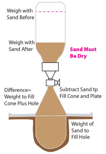
Sand Cone Density Method for Compaction Testing
Pros and Cons
| Pros | Cons |
|---|---|
| Accurate and reliable; a long history of accepted use | Tests may take 30 minutes or more to complete |
| ASTM standard test method | Heavy equipment in the area may need to pause operation briefly |
| Does not require extensive training | Alternative tests must be used where appreciable amounts of +1.5in (38mm) material are present |
| No licensing or permitting is required for use | Should not be used to test saturated, highly plastic soils |
| Equipment and materials are not hazardous | All excavated material must be carefully recovered |
| Equipment is cost-effective |
Rubber Balloon Test
Rubber Balloon Density test shares some similarities with the sand cone method. Like the sand cone method, a test hole is excavated, and the soil is carefully collected and set aside. A balloon density apparatus is positioned over the hole, and instead of using sand to measure volume, the calibrated water vessel is pressurized, forcing a rubber membrane into the excavation.
Graduations on the vessel are read to determine the amount of water displaced so the whole volume can be calculated. The test method is described in ASTM D2167 / AASHTO T 205 (withdrawn). The tests are a bit simpler to perform than the sand cone and can be repeated quickly since the water is retained in the vessel.
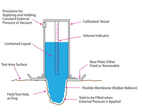
Rubber Balloon Method
Pros and Cons
| Pros | Cons |
|---|---|
| Accurate and reliable; a long history of accepted use | Tests may take 15-20 minutes or more to complete |
| ASTM standard test method | Balloon membranes can puncture during testing |
| Does not require extensive training | Intended for fine-grained or granular soils without appreciable amounts of coarse material |
| No licensing or permitting required for use | Should not be used to test soft saturated, highly plastic soils |
| Multiple tests can be performed without changing density media | All excavated material must be carefully removed |
| Equipment is cost-effective |
Moisture Content of Soil and Unit Weight Tests:
Moisture content and unit weight must be performed on retained soil samples from either a sand cone or rubber balloon tests to complete calculations for soil compaction. These tests are easily done in the laboratory but are often performed on-site to provide important compaction data quickly, to earthwork contractors and other concerned parties.
The chart below shows a few different methods that can be used for moisture determinations and there are a variety of scales and balances that can be used for weighing soil samples in laboratory or field settings.
ASTM Soil Moisture Tests
| ASTM Number | Test Method | Comments |
|---|---|---|
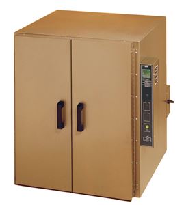
| D2216 | Laboratory oven determination | Most reliable, but delays reporting of results |
| D4643 | Microwave method | Faster than the oven method, but still delays reporting |
| D4944 | Calcium carbide gas pressure tester | Reliable, fast, and accurate field-testing method |
| D4959 | Moisture content by direct heating | Reliable results and can be performed in the field |
Nuclear Density Test
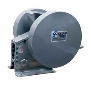
Nuclear density gauges determine soil density by measuring gamma radiation transmission between a probe containing a radioactive Cesium 137 (or other) source and Geiger-Mueller detection sensors in the base of the gauge. Dense soils allow fewer gamma particles to be detected in a given time period. Soil moisture is measured at the same time using a separate source of Americium 241.
A steel rod is driven into the soil at the test site, forming a pilot hole. The probe containing the radioactive source is lowered up to 12in (305mm) into the pilot hole, and radiation transmission is measured for one minute. This is known as a “direct transmission” test. Readings may also be taken in a “backscatter” mode where the probe is not extended from the base of the device. No pilot hole is required for this method, but the results are considered less reliable. Values are reported in wet and dry unit weights of soil, soil moisture contents, and percent compaction compared to laboratory or field Proctor moisture-density tests.
Nuclear density gauges are efficient on large projects requiring rapid results and multiple tests but are subject to many regulatory requirements and require advanced training and radiation dosage monitoring of personnel. Test methods are described in ASTM D6938 / AASHTO T 310.
Nuclear Gauge for Density and Moisture Soil Testing
Pros and Cons
| Pros | Cons |
|---|---|
| Density/moisture tests are complete in a few minutes | Testing equipment is expensive |
| ASTM standard test method | Regulatory requirements govern the storage, usage, transportation, and handling |
| Accuracy and repeatability are acceptable for field operations | Safety concerns require monitoring of personnel by dosimeter badges |
| Electronics can incorporate data logging and location reporting functions | Operators require advanced safety training and certification |
| The optimum method for large projects requiring many tests per day | Electronics can be sensitive to harsh environments |
| Can be used with a wide range of soil types | Readings are sensitive to excessive voids |
Beyond Test Results
Each of these different methods of performing soil compaction density tests has advantages and disadvantages. The absolute accuracy of any method is not a settled issue, but they all produce results that are reliable and can be accepted by design teams and regulatory authorities when performed properly.
The most important factor for proper earthwork installations is the expertise of knowledgeable personnel, whether they are technicians, equipment operators, or project superintendents. A compaction test shows that one small area meets the requirements of the specifications. Only a trained and experienced eye can confirm that the test is representative of overall site conditions.
We hope this blog post has helped you understand the methods and soil density testing equipment used to test the compaction of soils for construction operations.
Gilson Is Here to Help
Contact our testing experts for more information or to discuss your testing application.
Testing Resources
Standard Test Methods, Specifications, and Practices
Individual test methods and specifications referenced in our product descriptions, blog articles, and videos are available for review or purchase from the professional organizations noted.
- ASTM International (American Society for Testing and Materials)
- AASHTO (American Association of State Highway and Transportation Officials)
- ACI (American Concrete Institute)
- State DOTs (Departments of Transportation)
- ISO (International Organization for Standardization)
- BS (British Standards)
- EN (European Standards)