

Air entrained concrete mixes have greatly enhanced freeze/thaw durability and service life over plain concrete. Still, too much air content causes a significant reduction in strength, and too little is ineffective. Since the percentage of air specified is critical to how the mix performs, accurate tests for concrete air content are essential. Fortunately, they are easy to achieve.
The standard test methods ASTM C231 and AASHTO T 152 explain how to test concrete in pressure-type concrete air meters, and describes concrete air meter calibration in detail. The published calibration procedures seem complicated and intimidating at first glance; however, for meaningful results, they must be followed to the letter.
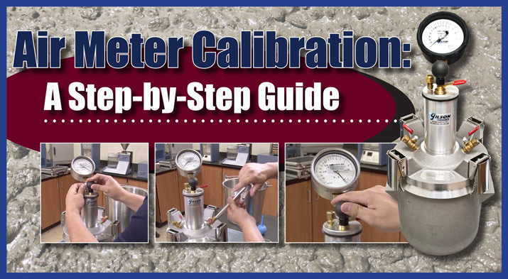
This blog post discusses the maintenance of Type B concrete pressure meters and breaks down into everyday language the steps for proper air meter calibration. Once understood, the practice isn’t hard to carry out and doesn’t take long. The calibration of Type A meters involves different steps and is described in C231, but not here.
Make Your Air Meters Last: Maintenance Rotations
Concrete air meters typically see some rough field usage, and their operators don’t always provide tender loving care for these units. Rotating an air meter into the lab for scheduled maintenance every three months is an opportunity to evaluate overall condition, check functionality, clean and repair, and of course, calibrate.
Perform cleaning, maintenance, and functional checks ahead of calibration since these operations might change the calibration slightly. Repair parts are readily available from the manufacturers.
- Cleaning
Concrete can accumulate and harden in dozens of joints and crevices in air meters, damaging petcocks, bleeder and pressure valves, clamps, and threads just by neglecting a quick cleaning while the concrete is fresh. Concrete accumulating in the measuring bowl can change calibration values, throwing off test results by a significant amount.
Performing a simple cleaning at the completion of a test saves hours of scraping and chipping and can reduce the number of ruined parts. Including an inexpensive scrub brush with the air meter field kit makes the task easier. Assigning personal responsibility for equipment upkeep helps as well.
- Maintenance & Operation
Scheduled inspection of basic meter condition reveals problems that call for repair or replacement and is pretty straightforward:
- Leaks are a common problem and are quickly isolated by pressurizing the air chamber and brushing soapy water over the joints and fittings, or by submerging the cover assembly (except for the gauge) in a water container. Any of the numerous gaskets and O-Rings used in the meter can fail from damage, dirt, or wear. The cover assembly can also be pressurized while on the measuring bowl to check for leaks between the lid and bowl. Correct these leaks by checking the condition of the gasket and adjusting the clamps but avoid making them too tight.
- Clamps are working parts that are often damaged or just out of adjustment because they are exposed. Most styles used on current air meters are easily adjustable to adequately secure the lid with no leakage and without excessive pressure.
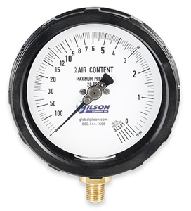
- Gauges on top of air meters are exposed and easily damaged, so it pays to have a rugged and durable unit. Glass lenses break, fog up, or get scratched, and the fittings can be damaged. Occasionally the gauge needle will be bent and rub against the glass, thus affecting readings.
- Pumps wear out from repetitive use, but a durable unit with quality parts will outlast cheaper models. Superior models have more reliable check valves, larger chambers, and longer strokes for faster, easier pressurization.
- Measuring bowls depend on smoothness and planeness of the rim for a tight seal with the cover gasket. Check the flange of the container for nicks and gouges that could affect the seal.
Concrete Air Meter Calibration Frequency
Gilson’s Technical Support Team often fields the question from our customers: “How often do I need to calibrate my concrete pressure meter?” For the Type B pressure meter, there are different values to calibrate for. The procedures are not difficult and are covered step-by-step in the ASTM and AASHTO test methods. The payoff is the confidence that your field tests will be consistently accurate.
- Initial Calibration is required before the meter is put into service for the first time. This procedure requires the additional steps of calibrating the cylindrical calibration vessel and the measuring bowl. Once this is done, these steps only need to be repeated occasionally to verify accuracy, or if the calibration vessel or measuring bowl is damaged or replaced.
- Verifying the initial pressure line is not required each time but is easy to check during other calibration procedures.
- Checking gauge accuracy is required at intervals not exceeding three months, or anytime an issue with accuracy is suspected. The required three-month interval is a good opportunity to give each meter a thorough cleaning and to check for damage and wear.
Before the First Calibration
Before you can perform the initial calibration of a Type B meter, you first must determine the volume of the calibration vessel against the capacity of the measuring bowl. The good news is that you only need to do this once unless there is a change in the calibration vessel or measuring bowl.
- Calibration vessel¹: Fill the vessel exactly full of water and weigh the vessel with water on a balance accurate to ±1.0% of the total weight. Subtract the tare weight from the total weight to find the mass of the water (w).
- Measuring bowl: Put a thin film of grease on the flange and fill it with water. Slide a glass plate over the rim to ensure it is full. Weigh together on a scale or balance accurate to ±1.0% of the total weight. Subtract the weight of the tare and glass plate from the total weight to find the mass of the water (W).
- Calculate the effective volume of the calibration vessel as a percent of the total volume of the measuring bowl (R). R = w/W
It’s common field practice also to use the measuring bowl of the air meter to perform ASTM C29 and C138/AASHTO T 19 and T 121 density and unit weight determinations for aggregate and concrete. Although not required to calibrate the air meter, two quick steps of measuring the water temperature and looking up the density of water at that temperature allow an easy calculation to document the bowl volume for these tests: Volume = Weight of Water (W)/Density of Water (interpolated from the chart below)
Density of Water
| °C | °F | kg/m3 | lb/ft³ |
|---|---|---|---|
| 15.6 | 60 | 999.01 | 62.366 |
| 18.3 | 65 | 998.54 | 62.336 |
| 21.1 | 70 | 997.97 | 62.301 |
| 23 | 73.4 | 997.54 | 62.274 |
| 23.9 | 75 | 997.32 | 62.261 |
| 26.7 | 80 | 996.59 | 62.216 |
| 29.4 | 85 | 995.83 | 62.166 |
Verify the Initial Pressure Line
Verifying proper placement of the initial pressure line on the gauge of the air meter is a simple operation. Like the volumetric measurements above, it only needs to be performed once initially and then occasionally to check performance. Perform this step while checking gauge accuracy, as noted below.
The assembled meter with cover is filled with water, removing all entrapped air bubbles by adding the water through the open petcocks. The air chamber is pressurized by pumping until the gauge needle stabilizes at the initial pressure line. After closing the petcocks, the pressurized air is released into the bowl using the needle valve lever. Tap the gauge lightly until the indicator hand stabilizes. The gauge hand should indicate 0.0±0.1%. You can correct the initial pressure line by substituting new values until the final readings are acceptable. Do not adjust the gauge hand itself at this point. Record the new initial pressure line.
Check Gauge Accuracy
Check accuracy of graduations on the face of the pressure gauge at intervals of no more than three months, or whenever there is a question of gauge accuracy. Several steps must be followed sequentially for proper calibration of the meter.
- Start with the measuring bowl full of room temperature water.
- Thread the short, straight piece of metal tubing into the threaded opening for the petcock on the underside of the base. Clamp the cover into place on the bowl with the tube extending down into the water. Ensure that both petcocks are open.
- Using the bulb syringe, add water through the petcock with the tube to force all air out through the opposite petcock.
- Use the hand pump to pressurize the air chamber until the gauge hand reaches the initial pressure line. Allow the air to cool for a few seconds, then pump or bleed off air as needed and tap the gauge lightly to stabilize the indicating hand.
- Close both petcocks and immediately press the needle valve lever to release air from the chamber into the measuring bowl. Tap the gauge lightly while holding the release down until the reading is stable. The indicator should indicate 0.0±0.1% of air content.
- Screw the curved extension tube into the top opening of the threaded petcock and leave the open end pointing downward.
- Position the calibration vessel directly under the curved tube on a level surface.
- Carefully press the needle valve lever to regulate the flow of water out of the bowl and into the calibration vessel until it is level full.
- Release air pressure by opening the opposite petcock completely.
- Open the petcock with the tube, allowing water to flow back into the bowl. The air in the base will now match the volume of the calibration vessel (usually 5%).
- Leaving both petcocks open, again pressurize the air chamber by pumping, using the same sequence to stabilize the gauge hand at the initial pressure line.
- Close the petcocks and immediately press the needle valve lever. Stabilize the gauge as before. The gauge should read 5.0±0.1%. If it does not appear to read correctly after two or more sequences, follow the manufacturer’s instructions to adjust the indicator needle to 5%.
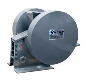
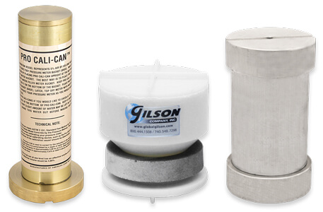
On-the-Spot Verification
Concrete air meter calibrators provide fast, on-the-spot field verification of air meter gauge accuracy and can pinpoint problems early. To use them, place one at the bottom of an air meter base, fill the base with water, and perform the standard air test procedure. Instant results resolve questions and avoid disputes over accuracy. They are cost-effective and compact enough to include in every technician’s field kit.
Aggregate Correction Factor
The procedure for determination of an aggregate correction factor is in the standard test method and should be performed whenever there is a change in the aggregate source. Air entrapped in aggregate particles doesn’t play a large role in overall freeze/thaw durability of concrete, but if not accounted for, it can create misleading test results.
A representative sample of fine and coarse aggregates in proportions equivalent to the concrete mix design is consolidated into water in the measuring bowl. The aggregate is left to soak for a prescribed period, a specified amount of water is drawn away, and a conventional air test is performed. Calculate the correction factor by subtracting the volume of the calibration vessel from the air content reading of the aggregate sample.
We hope this blog post has helped you understand the maintenance and calibration procedures for Type B concrete air meters.
Gilson Is Here to Help
Contact our testing experts for more information or to discuss your testing application.
Testing Resources
Standard Test Methods, Specifications, and Practices
Individual test methods and specifications referenced in our product descriptions, blog articles, and videos are available for review or purchase from the professional organizations noted.
- ASTM International (American Society for Testing and Materials)
- AASHTO (American Association of State Highway and Transportation Officials)
- ACI (American Concrete Institute)
- State DOTs (Departments of Transportation)
- ISO (International Organization for Standardization)
- BS (British Standards)
- EN (European Standards)