


Soil Electrical Resistivity Testing
Prospecting for mineral ores, designing structural foundations, corrosion protection for buried metal structures, and confirming reliable electrical grounding are activities that don’t seem to have a lot in common. Still, there is one test method that unites all these disciplines.
Soil electrical resistivity testing quantifies how readily electrical currents pass through a soil medium. Resistivity, or its inverse value of conductivity, is a crucial soil property in the different disciplines of geotechnical engineering, corrosion mitigation, and electrical distribution systems. Electrical resistivity characterizes the properties of soil, rock, pore fluids, and buried objects.
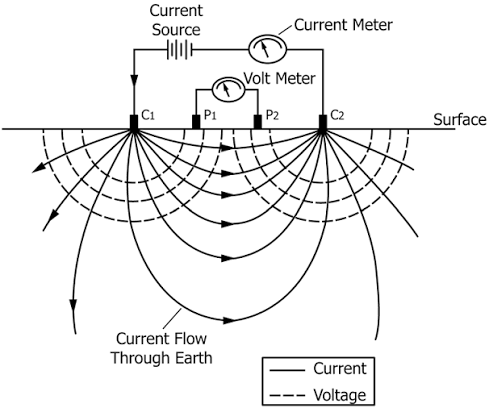
Soil resistivity values are expressed as bulk resistivity in Ohms per centimeter (Ohm-cm) units. This bulk or volume resistivity number is inherent to that particular soil regardless of the shape or size of the sample.
How Do I Test for Resistivity and What Will it Tell Me?
Test methods for soil resistivity are similar for most applications. Four metal electrodes are driven into the soil surface in a predetermined pattern at a specified spacing in the most common configuration. Direct current is passed through the two current electrodes, and resistivity is determined by measuring the voltage drop at the two potential electrodes.
Resistivity values of soil are based on its mineral and chemical composition. The chart below shows typical resistance values in various material and groundwater types.
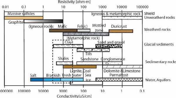
Typical Resistivity Values in Ω-m for Different Materials (From ASTM D6431)
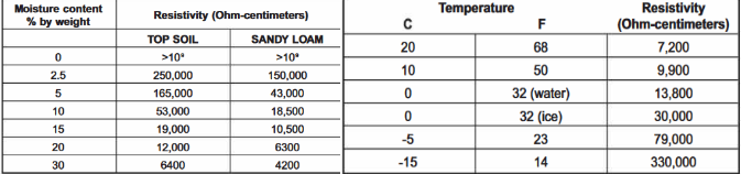
Seasonal variations in moisture content and soil temperature cause sizable variations of resistance in the same soils, as noted in the examples on these two charts:
Specialized resistivity testing equipment, purpose-built for soil analysis, is effective in filtering out unwanted electrical “noise” generated by power lines, electrical substations, and electric light-rail train tracks. Interference from these sources can trigger significant errors in test results.
A particularly useful characteristic of the resistivity test is that the spacing of the probes easily regulates the depth of readings. It is a simple 1:1 ratio; a probe spacing of 10ft (3m) yields average data up to a depth of 10ft (3m).
Soil resistivity readings with multiple spacing, orientation, and electrode depths define soil classes, strata, and groundwater properties. Shorter probe spacing yields better measurements in shallower soils. As the probe spacing increases, readings characterize greater depths and a larger horizontal area. The two most popular techniques used in field soil resistivity studies are both “4-pin” methods.
The Wenner method uses two current and two potential electrodes spaced at equal distances in an inline pattern. This method requires a lower current for a given depth and has a higher signal-to-noise ratio, making it less sensitive to outside electrical interference.
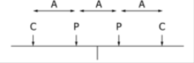
Wenner Electrode Layout
For the Wenner four-point method, the formula to calculate the resistivity of soil, ρ, in ohm-meter (Ω-m) units is:
ρ = 2πaR
Where:
- a = Electrode spacing in meters (for ohm-cm units, use spacing in centimeters).
- R = Resistance value in ohms (Ω)
For example: with electrodes spaced at 6.1m (20ft), the meter shows a resistance value of 15Ω. Using the formula above and the 1:1 ratio of electrode spacing to reading depth, the average soil resistivity value is calculated at 574.9Ω-m to a depth of 6.1m.
The Schlumberger (pronounced shlum-bur-shay) method uses unequal spacing between four inline electrodes. This technique is less popular than the Wenner method but also less susceptible to continuity problems and the influence of nearby geologic features. It requires less repositioning of electrodes between readings.
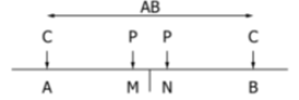
Schlumberger Electrode Layout
To calculate the apparent soil resistivity in ohm-meter (Ω-m) units using the Schlumberger method:
ρ = π [((AB/2)2 − (MN/2)2) / MN] × R
Where:
- AB = Distance between current electrodes
- MN = Distance between potential electrodes
- R = Resistance value in ohms (Ω)
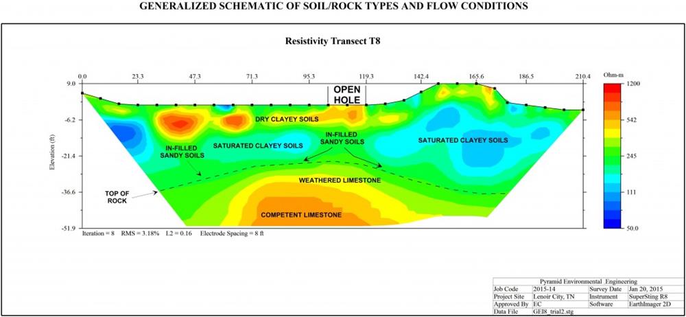
Schematic of Soil and Rock Types
Soil Resistivity Tests for Geophysical Surveys and Geotechnical Investigations
Geophysical surveys and geotechnical investigations use soil resistivity to look for some of the same things for different reasons. These are field tests performed on-site to document existing conditions.
Geophysical surveys identify mineral ore deposits, depth to bedrock, and geological and archaeological features. These studies assemble data to depict and map existing subsurface conditions.
Geotechnical investigations are performed to provide information for the design of foundations or embankments and to mitigate risk. Soil resistivity supplements test borings and penetrometer values to assess the composition and density of soil and rock materials and discover subsurface conditions.
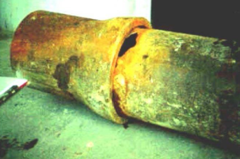
Corrosion damage to a Pipeline Fitting
Soil Resistivity Testing for Corrosion Protection of Buried Structures
Corrosion rate directly impacts the service life of buried ferrous metals. Soil resistivity testing assesses the corrosivity of soils and influences the selection of metal types and coatings and cathodic protection design.
Resistivity tests performed before installing structures help determine which metal alloys and protective coatings will be most corrosion-resistant in the specific environment. Accurate corrosion-rate estimates enable cost-effective designs that specify the type, size, and quantity of sacrificial anodes in cathodic protection systems.
| Soil Resistivity (ohm-cm) | Corrosivity Rating |
|---|---|
| >20,000 | Essentially non-corrosive |
| 10,000 to 20,000 | Mildly corrosive |
| 5,000 to 10,000 | Moderately corrosive |
| 3,000 to 5,000 | Corrosive |
| 1,000 to 3,000 | Highly corrosive |
| <1,000 | Extremely corrosive |
Soil Resistivity Relationship to Corrosion Activity
Anytime metal structures, utilities, or pipelines are embedded in direct contact with soil, there is a risk that they will be damaged by corrosion. Properties of the mineral content, pH, electrolyte profile, temperature, and moisture content of the soil govern its electrical resistivity, which determines the corrosion rate. Lower resistivity numbers indicate more active corrosion rates. In other words, a soil medium that is a better conductor of electrical current corrodes metal objects more quickly.

Lightning Strike at a Power Distribution Station
Soil Resistivity Testing for Electrical Grounding Networks
Electrical grounding networks for power stations, cellular and telecommunications towers, lightning protection, and other applications range from simple layouts to complex systems that require careful planning. A well-designed electrical grounding system improves equipment reliability and prevents damage caused by lightning strikes and/or fault events.
Accurate information from soil resistivity testing is an essential part of any grounding design. Identifying areas of low soil resistivity is the easiest path to building cost-effective grounding installations.
The Wenner method is the most common testing technique for grounding layout. The requirements of the project dictate probe spacing and penetration depths. Most grounding apparatus is buried at depths of 1.5ft to 3ft (0.5m to 1m) below the surface, so shallow readings are essential.
Soil Resistivity Testing: A Guide to Essential Equipment
Gilson recommends soil resistivity apparatus from M.C. Miller for accurate results, reliable performance, and ease of operation. Select a rugged and simple-to-operate analog or digital soil resistance meter and pair it with a standard test kit that includes all the components necessary for complete resistivity analysis in the laboratory or field. The meters and test kit components are designed by experienced professionals to meet the requirements of published test methods for soil resistivity testing.
Soil Resistivity Test Kit contains all the components needed for resistivity testing using the four-pin Wenner method. Components are housed in a shockproof heavy plastic Pelican™ case with lockable latches. The foam-lined case includes a cut-out to hold an Analog or Digital Soil Resistance Meter, required for operation and sold separately. Individual Kit components are also available separately:
- Soil Box for laboratory samples is adaptable for two-pin or four-pin operation using ASTM test methods G57 or AASHTO T 288 and ASTM G187. The box has a volume of 270cm3, a cross-sectional area of 12.8cm2, and sturdy plexiglass construction. Removable pins and rounded corners ensure easy clean-up.
- Soil Pins are heavy 3/8in (0.95cm) diameter stainless steel rods with T-handles and pointed tips for easy manual installation in soil. Length is adequate for testing depths up to 18in (46cm).
- Color-Coded Lead Wires are 4ft (1.2m) long for connection of the resistivity meter to the cable reel. The leads are supplied with banana plugs at both ends for secure connections to the terminals.
- Reel with Resistivity Cables offers convenient storage, and easy deployment of the four included resistivity cables at electrode spacings of up to 20ft (6m). The industrial-grade thermoplastic wheel is mounted on a zinc-coated steel frame with a built-in handle. An integral drum brake prevents over-reeling, and four color-coded terminals are built-in.
Analog Soil Resistance Meter features an analog dial gauge for reliable operation and eight selectable ranges of resistance values. The total range is from 0.01 Ohms to 1.1 Mega-Ohms. Four color-coded terminals on the meter accept plugs from the lead wires.
The rugged, weather-resistant plastic case protects the meter during storage, transport, or use. The lid is removable for easy access to controls and terminals during use. Proven electronic circuitry design prevents stray interference. Readily available C-cell batteries power the meter.
Digital Soil Resistance Meter features auto-ranging operation for readings from 0.01 Ohms to 1.1 Mega-Ohms. Bluetooth integration allows logging results in ohm-cm units directly to Android devices and PCs with the included ProCP Soil Resistivity software. Resistivity data can be time-stamped and GPS-located with the user’s device. Plugs from the electrode lead wires plug into the four color-coded terminals.
The rugged, weather-resistant plastic case protects the meter during storage, transport, or use, and proven electronic circuitry design prevents stray interference. The removable lid allows easy access to controls and terminals during use. Readily available D-cell batteries power the meter.
Standard Test Methods and Guides for Resistivity Testing
Several ASTM standards are widely used for geophysical/geotechnical, corrosion protection, and electrical grounding applications.
ASTM D6431 provides guidance on commonly used resistivity methods, their limitations, electrode geometry, spacing, and typical soil and rock resistivity ranges for subsurface site characterization.
ASTM D6429 is a guide to selecting geophysical methods for geologic, geotechnical, hydrologic, and environmental site studies and forensic and archaeological applications. The guide does not describe the specific procedures for conducting geophysical surveys.
ASTM D420 is a guide to the selection of methods for site characterization, including soil resistivity, for geotechnical design and construction applications. Sampling or in-situ testing confirms soil and rock formations and groundwater conditions identified by resistivity.
ASTM G57 covers the equipment and procedures used in the Wenner 4-pin method to measure soil resistivity in place. Four electrodes are driven into the soil at predetermined and equal spacings. The test may also be performed on representative samples compacted into a soil box with four fixed electrodes.
ASTM G187 and AASHTO T 288 test methods describe soil resistivity tests performed on laboratory samples compacted into a soil box with two fixed electrodes.
We hope this blog article has helped you understand the different applications for soil electrical resistivity testing and the equipment required. Please contact Gilson’s testing experts for help with your applications.
Gilson Is Here to Help
Contact our testing experts for more information or to discuss your testing application.
Testing Resources
Standard Test Methods, Specifications, and Practices
Individual test methods and specifications referenced in our product descriptions, blog articles, and videos are available for review or purchase from the professional organizations noted.
- ASTM International (American Society for Testing and Materials)
- AASHTO (American Association of State Highway and Transportation Officials)
- ACI (American Concrete Institute)
- State DOTs (Departments of Transportation)
- ISO (International Organization for Standardization)
- BS (British Standards)
- EN (European Standards)