


The history of soil shear testing stretches back further than you might think. If Karl von Terzaghi is known as the “father of modern soil mechanics,” we would have to label Charles-Augustin de Coulomb as its grandfather. Best known for his work in electrostatic attraction (Coulomb’s law), this French engineer also pioneered early thought, and possibly actual shear tests, related to soil strength and lateral earth pressures on structures in 1773. Another French engineer, Alexandre Collin, developed a direct shear testing apparatus in 1846 for use in his work with slope stability of cohesive soils. In 1932, Arthur Casagrande, a contemporary of and onetime assistant to Terzaghi, refined the design for a new shear box during research at Harvard University.
Why is Direct Shear Testing Important?
Direct shear test of soil is a relatively simple soil mechanics test run on cohesive or non-cohesive samples of undisturbed or remolded soil materials. The procedure is cost-effective for characterizing basic soil properties. Analysis of the results provides data for geotechnical engineers to calculate soil bearing capacity, slope stability, lateral earth pressures on retaining structures, and pavement designs.
What is the Direct Shear Test of Soil?
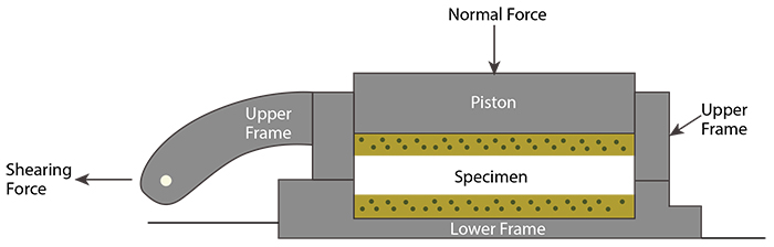
A shear box, or shear ring, contains the soil specimen and consists of two halves, stacked vertically. A direct shear machine applies a predetermined vertical load (normal stress) to the soil specimen in the shear box assembly. The applied normal stresses depend on the loads anticipated in the design. The bottom half of the shear box is held in place while the shear machine applies a controlled horizontal force to move the upper half in one direction. The deformation and force applied to the sample are measured and recorded until there is a shear failure.
Usually, different normal stresses are applied to three test specimens from the same sample to create a stress-strain curve for each. Some direct shear machines also reverse the lateral force after directly shearing the soil specimen to measure the residual shear strength. Pore water pressure is allowed to dissipate through porous stones during soil direct shear tests. Because of the short sample height and the narrow shear plane of the direct shear specimen, the failure plane of the test specimen may not represent the weakest plane in the soil layer. With care during sample preparation, it is possible to position a recognizable weak plane or layer interface within the shear plane. In this blog post, we’ll focus on that method, as described in ASTM D3080 and AASHTO T 236.
This article serves as an informational guide to equipment and techniques used for the direct shear test of soils as outlined in ASTM D3080 and AASHTO T 236. The information contained herein does not supersede the specifications or test protocol of these published test methods.
What Direct Shear Equipment is Needed?
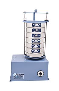
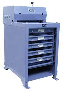
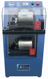
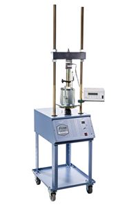
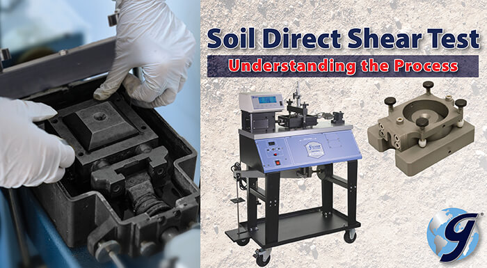
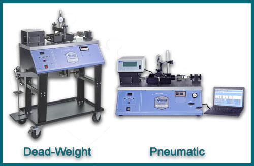
Modern direct shear machines range from tabletop models using pneumatic pressure methods to apply the normal (vertical) loads to the soil specimens, to floor-standing units with dead-weight masses to apply normal loads. Both versions use advanced, precisely controlled stepper motors to provide the lateral displacement or horizontal shear force. These machines can measure force and deformation with simple analog dial gauges and load ring components, or sophisticated electronic load cells and linear variable displacement transducers (LVDTs). Digital components can measure, log, graph, and store test results using advanced data acquisition software.
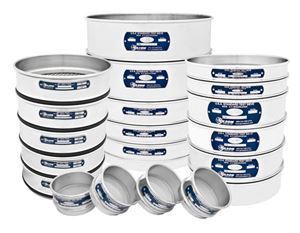
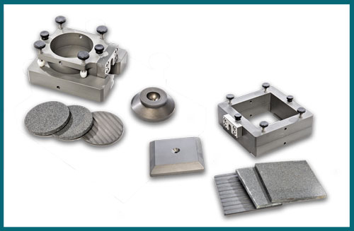
Shear boxes, sometimes called shear rings, hold the soil specimens during testing and are available in square or circular shapes in a variety of sizes. The main sections of the boxes should be constructed with similar corrosion-resistant materials to resist galvanic action. Adjustment screws precisely control the gap between the upper and lower halves of the box. The shear box mounts in a bowl on the machine, which acts as both an anchor for the box and a container for water to submerge the specimen.
A 2.5in (63.5mm) diameter shear box is a popular size, often used for samples trimmed down from undisturbed thin-walled tube samplers (Shelby tubes). Porous stones with filter paper inserts are placed on the top and bottom surfaces of the shear specimen when mounted in the shear box to allow pore water pressure to dissipate during normal or lateral loading.
Sample Preparation: The Important First Step
Proper sample preparation has a direct impact on the accuracy of the direct shear test. Preparation of the specimens is best performed in a humid environment to prevent loss of moisture with an initial sample large enough to provide at least three identical test specimens. Laboratory-prepared samples can be remolded directly into the shear box following the procedure specified in the test methods.
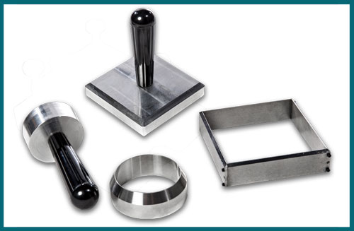
When testing undisturbed soil materials, trim down a test specimen to the final size from a slightly larger and thicker initial sample. Place it on a flat, non-absorbent, polished surface such as a glass plate. Press a specimen cutter with sharp cutting edges and the same inside dimensions as the shear box into the sample about 1/4in (6mm) or so. Using a wire saw or sharp trimming knife, progressively trim small amounts of soil away from the beveled cutting edge while pushing in the cutter. Alternately, some soft soils may be trimmed by just gently forcing the specimen cutter directly into the material. Use care to avoid compressing the specimen or disturbing sensitive soil features. Errors in test results most often arise during trimming or when transferring the test sample from the cutter to the shear box. After the soil protrudes from the top of the specimen cutter, trim the top and bottom surfaces flush.
To move the trimmed specimen into the shear box, position the cutter with soil specimen cutting edge down on top of the box, assembled with the bottom porous stone and filter paper in place. Select the proper extruder and press the soil specimen out of the cutter and into the shear box with a smooth, continuous motion. A piece of waxed paper cut to size between the extruder and specimen can prevent soil from sticking to the extruder surface. After placing the top filter and porous stone, the assembled shear box is ready for placement in the direct shear machine.
Note: Clogged pores of the porous stones can impede the drainage of pore water and affect test results. Clean porous stones between each use by boiling them in water.
Performing the Direct Shear Test
The normal stress loads for initial consolidation of the specimen are usually selected to represent field conditions by those requesting the test. A small normal load for seating is applied after the shear box is placed in the shear device. After proper alignment of the components, apply the main normal load, either incrementally or in one step, and inundate the sample with water. Intervals for application of load increments may be up to 24 hours, and deformation is measured periodically to determine consolidation. Deformation and time data from this phase determine the shear rate during horizontal loading. The shear rate must be slow enough to allow any significant pore pressures to dissipate before failure. The ASTM/AASHTO test methods do not specify the exact values used to perform the direct shear test. These parameters are determined by the stakeholders requesting the tests or from carefully calculated equations noted in the test method.
The lateral movement device is activated to begin the test once the shear rates have been calculated and set. Record periodic readings of vertical and lateral displacement, time, and loads. During this process, carefully maintain the gap between the upper and lower halves of the shear box. It may be necessary to stop the test and reset the gap opening to avoid interference. Shear the specimen to at least 10% relative displacement or a point provided by the specifying agency. Once the shear test is complete, remove the shear box and manually separate the two halves by sliding them apart in the direction of shearing. A sketch or photograph should document the appearance of the failure surface. Remove the specimen now to determine the water content and calculate dry mass. The final test report must include normal loads and rate of shear, information and graphic plots of deformation versus time from normal and lateral loads, observations of the shear surface, pre-test and post-test moisture content and wet density, sample type, and identification, and more, as noted in the test methods.
We hope that you have found this blog post helpful in understanding the procedures and equipment used to perform the direct shear test of soils by the noted ASTM/AASHTO methods. Gilson offers a complete line of soil direct shear equipment and accessories, including models for measuring residual shear strength. Please contact us with questions or to discuss your application.