


Testing the asphalt content of a given sample is important to ensure that the properties of a material being laid down match what’s called for in the mix design.
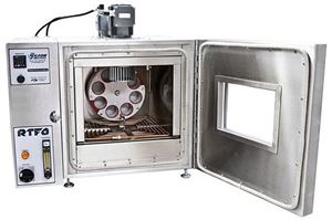
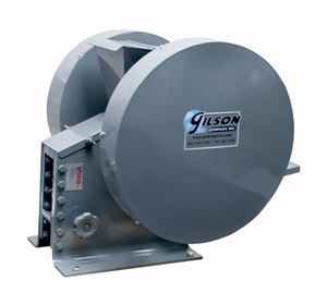
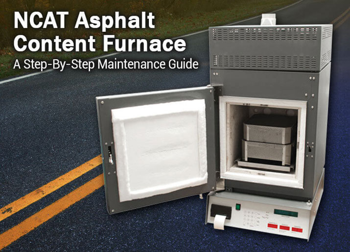
Today’s post will focus exclusively on the NCAT Asphalt Content Furnace. If you need a refresher, this machine is used to burn away asphalt, making it possible to calculate asphalt content and to perform a gradation on the aggregate left behind. To assure the best performance from your furnace, it’s essential to follow some basic weekly maintenance procedures. We’ll break it down for you with this easy step-by-step guide with our list of do’s and don’ts and maintenance help for the NCAT.
Maintenance Checklist:
Lift Check
If you are experiencing a long burn time, we recommend performing a lift check. This helps check the efficiency of the blower or exhaust system.
- With the furnace chamber cold, turn on the furnace and hit the start button.
- Watch the weight display window and note numbers appearing. On furnaces with serial numbers beginning with 859 or 945, you should see numbers of -3 to -6g. For furnaces with serial numbers beginning with 1087 or 1275, you should see numbers from -2 to -3g.
- The blower is now attempting to lift the weighing platform off the four ceramic tubes that go down to the top of the scale/load cell. The higher the numbers, the cleaner your furnace blower and exhaust chamber; Lower numbers indicate a buildup of soot in the blower/exhaust system.
- Refer to your owner’s manual for cleaning instructions.
- Allow the furnace to run for 30-seconds as shown in the elapsed time window and hit the stop button.
- Allow the furnace to continue heating for an additional 3 minutes and then turn the furnace off.
Heating Element Check
It’s important to remember that a clean system increases efficiency and lowers burn times. If your element is faulty, this may increase test time, altering results.
First, determine which series your machine falls under. Check the first three or four digits of the serial number on the plate located on the back of your furnace to determine which element check applies to your particular furnace.
Series 859 and 945 have the filter assembly hanging down inside the top of the chamber and have four heating elements.
- After the lift check is complete and the furnace chamber has warmed up, make sure the green power switch is turned off.
- Open the chamber door, and with your hand, touch the two side plates. They should be starting to warm up. If one or more of the plates feel cold to the touch, they should be replaced.
Tip: The back wall of the chamber does not have an element plate.
Series 1087 and 1275 have the filter assembly built-in above the ignition chamber and have five heating elements.
- Check the four elements inside the chamber the same way as described above, with your hand. Proceed to step 2 to check the fifth heating element, above the chamber.
- With the chamber at regular ignition temperature (538˚C), turn the furnace off using the green power switch. Hold down the #7 key on the keypad and turn the furnace back on with the green power switch.
- After a few seconds, the furnace will “beep” and you can take your finger off the #7 key. You will now see two temperatures displayed. The chamber temp display will show the actual chamber temperature. The percent loss window will show the actual filter element temperature. It should read 750˚C. If it is considerably lower (around 500˚C) the filter heating element is burned out and needs to be replaced.
- Turn the furnace back off and then back on without holding down any other keys to return the furnace to burn mode.
Dos:
- Do perform weekly performance and maintenance checks for your furnace
- Do perform a weekly lift check to monitor airflow through the furnace chamber. The lower the airflow, the longer the burn time
- Do check the heating element when the power switch is turned off to determine if plates need to be replaced
- Do try to keep your furnace as clean and white as possible
- Do occasionally remove the four ceramic tubes that go through the floor of the chamber and examine for volatiles that could drip onto the scale. If there are buildup, place tubes in the chamber during the weekly 560˚C burnout
Don’ts:
- Don’t forget to preheat samples of aggregate and asphalt to a constant weight when preparing for the standard ignition method. This can minimize inconsistent asphalt content values.
- Don’t let unburned hydrocarbons or other volatiles build-ups, they will damage the heating element wires. To prevent buildup, periodically elevate the chamber temperature to 560˚C and allow the furnace to sit at that temperature for two hours.
- Don’t ignore signs of darkening on the insulating material on the back of the door. This indicates an air leak, requiring adjustment of the door and latch assembly.
Equipment Issues
What do I do if the printer stops operating?
It’s possible that someone accidentally turned off the printer switch. Check to make sure the switch is on. The paper feed can jam and overload the printer drive motor. The motor will shut itself off if this happens. The printer paper should always feed over the top of the roll of paper. To restart the printer, lower the control panel and locate the back of the printer housing. There is a wide gray ribbon cable attached to the back. Disconnect that ribbon cable, count to 10, and then re-attach the ribbon cable. This should reboot the printer when you turn the power back on. If it does not reboot, you may need to purchase a new printer.
How do I install new element plates?
Loosen the clamps and slide a piece of plastic tubing, such as straw, over the old lead wire from the rear of the furnace before removing the element plate. After you have removed the old plate and have the new element into place, feed the lead wires through the plastic tubing. This makes it easier to find the holes. After the element plates have been pushed in as far as they will go, slide off the tubes, tighten the clamps and ensure that the element wires are centered in the clamping assembly. Then, cut off the excess wire.
Did we miss a maintenance question or need a manual, contact our Tech Experts for assistance.